QoS Values Calculator v3 (CoS, ToS, ToS HEX, DSCP, AF, IPP, CS, DP, ECN)

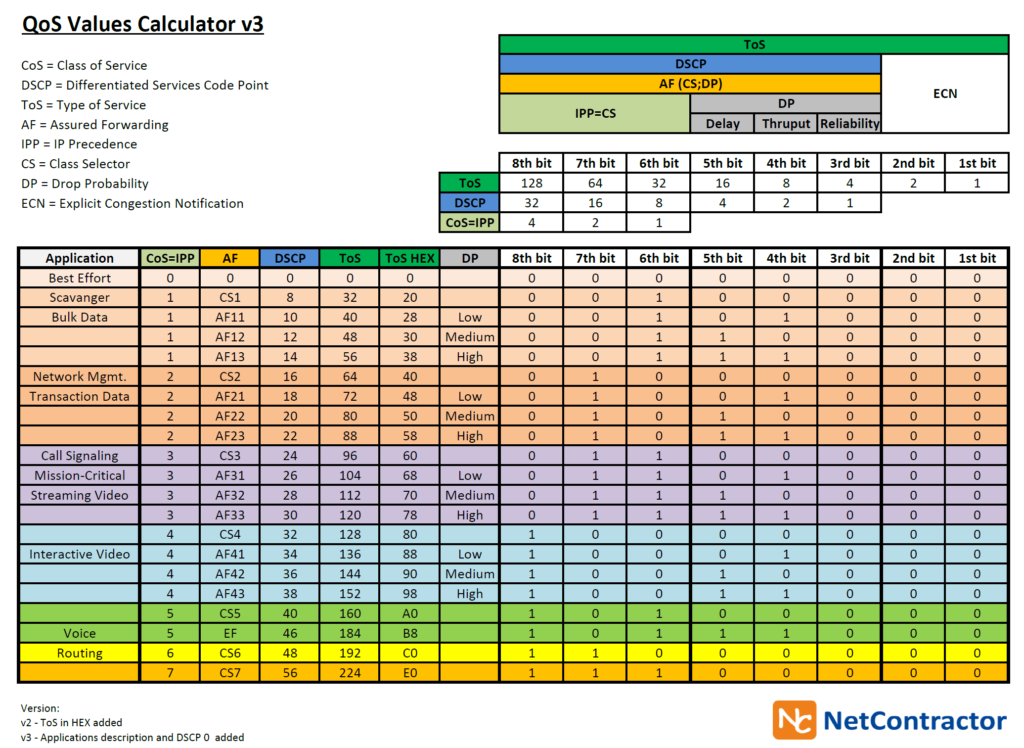
This post has been viewed almost 100k times from 2009 when I first time published the image – shock :). If there is still possibility to do something better I try ;). I had to move it from my old blog to new one.

Here you are version 3 of QoS Values Calculator.

I have added applications description and DSCP 0.

Do you think that something is still missing? 🙂

QoS-Values-Calculator-v3.jpg

QoS Values Calculator v3 in PDF format you can find here to download.

ISAKMP and IPsec lifetimes

I would like to sum up important issue regarding ISAKMP and IPsec lifetimes.

ISAKMP life is always set based on the Initiator ISAKMP lifetime even if its higher then ISAKMP lifetime of the responder.

IPsec lifetime is always set to the lowest value of the IPsec peer.

IKE Phase -1 life time should be greater than IKE Phase-2 life time .

86400 sec (1 day) is a common default value for Phase 1 and 3600 (1 hour) is a common value for Phase 2.

A difference between IKEv1 and IKEv2 is that in IKEv1 SA lifetimes were negotiated. In IKEv2, each end of the SA is responsible for enforcing its own lifetime policy on the SA and rekeying the SA when necessary. If the two ends have different lifetime policies, the end with the shorter lifetime will end up always being the one to request the rekeying.

Useful Command – show control-plane host open-ports

Here you are the first post from the Useful command series.

Have you ever wonder how to figure out under what ports your router is listening, just take a look (try also nice command like show ip sockets detail)

R1#show control-plane host open-ports
Active internet connections (servers and established)
Prot Local Address Foreign Address Service State
tcp *:22 *:0 SSH-Server LISTEN
tcp *:23 *:0 Telnet LISTEN
tcp *:80 *:0 HTTP CORE LISTEN
tcp *:443 *:0 HTTP CORE LISTEN
tcp *:22 10.0.12.2:59470 SSH-Server ESTABLIS
udp *:67 *:0 DHCPD Receive LISTEN
udp *:56186 *:0 IP SNMP LISTEN
udp *:161 *:0 IP SNMP LISTEN
udp *:162 *:0 IP SNMP LISTEN

NAT and VPN issue

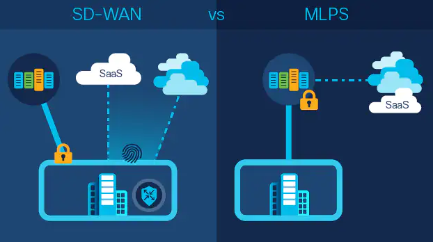
Here you are very typical architecture. Local Internet access and site to site VPN at the same router – easy case. To deploy this kind of configuration almost always we have to engage IPSec VPN and NAT at one platform. What does NAT imply for IPSec – let’s answer this question.

First we have to take a look at Cisco IOS order of operations. NAT is before encryption, what is means that traffic that needs to be encrypted will be first NATed then encypted. Mostly our crypto ACL that defines interesting traffic for encyption matches our source inside LAN subnet and remote end subnet IP. Once we add default NAT configuration, IPSec will not work properly. Traffic will never match crypto ACL because first will be translated and source IP will change (depends on NAT configuration) to outside interface IP or to dynamic IP defined in NAT pool.

To resolve this issue we have to exclude traffic that needs to be encrypted from NAT translation. Here you are quick configuration example how to proceed.

Assumptions:

Traffic from subnet 10.0.1.0/24 to 10.0.3.0/24 needs to be encrypted. Remaining traffic from 10.0.1.0/24 to Internet needs to be translated to outside interface IP.

Solution:

Define two ACLs. First needs to match VPN traffic (you can leverage of course crypto ACL that is already used by IPSec crypto map), second will define NAT traffic. Then create route map with two statements, in first statement we have to use deny key word and match crypto ACL, second permit statement will match NAT ACL. Route map has to be assigned under to ip nat inside configuration that describes traffic that will be translated. That’s all. Here you are how it looks like from configuration perspective.

ip access-list extended NAT
permit ip 10.0.1.0 0.0.0.255 any
ip access-list extended VPN
permit ip 10.0.1.0 0.0.0.255 10.0.3.0 0.0.0.255
!
route-map NAT deny 10
match ip address VPN
!
route-map NAT permit 20
match ip address NAT
!
ip nat inside source route-map NAT interface FastEthernet0/0 overload
!
interface FastEthernet0/0
ip nat outside
crypto map MAPA

NAT/PAT vs. traffic sourced from router

I can bet that you say that to configure NAT/PAT, ip nat inside and ip nat outside commands are always needed. I will show you example where we can translate IPs just with ip nat outside.

Specific exception is traffic generated from the router itself. Let’s play with NAT, configure PAT with simple ACL and compare difference for traffic generated from host that resides behind the router and for traffic from the router itself.

I would to translate all traffic from LAN network to Internet and will use fa0/0 interface IP. Instead use specific subnet IP I’m going to configure any/any in ACL (this will make me in trouble ;)). I just configure ip nat outside command under fa0/0 interface that simulates internet subnet.

Here you are my base config. R1 and R2 are connected directly via fa0/0 interfaces.

interface FastEthernet0/0
ip address 10.0.12.1 255.255.255.0
ip nat outside
ip virtual-reassembly
duplex auto
speed auto
!
interface FastEthernet0/1
ip address 192.168.1.210 255.255.255.0
duplex auto
speed auto
!
ip access-list extended NAT
permit ip any any
!
ip nat inside source list NAT interface FastEthernet0/0 overload

Let’s first generate telnet traffic from the host.
R2#show users
Line User Host(s) Idle Location
* 0 con 0 idle 00:00:00
66 vty 0 idle 00:00:15 192.168.1.105

As you see user has been connected from 192.168.1.105.

R1#sh ip nat translations
R1#

At R1 no translation appear, so NAT does not work and user’s telnet traffic has been simply routed with translation. To resolve this problem ip nat inside under int fa0/1 needs to be added.
Before we add it let’s generate test traffic from router itself.

R1#telnet 10.0.12.2 /source-interface fa0/1
Trying 10.0.12.2 ... Open
User Access Verification
Password:

R2#sh users
Line User Host(s) Idle Location
* 0 con 0 idle 00:00:00
67 vty 1 idle 00:00:34 10.0.12.1

NAT is working fine without ip nat inside even if we generated traffic with source fa0/1, telnet traffic has been translated to fa0/0 10.0.12.1.

R1#sh ip nat translations
Pro Inside global Inside local Outside local Outside global
tcp 10.0.12.1:28276 192.168.1.210:28276 10.0.12.2:23 10.0.12.2:23

Translation has been added.
What about traffic generated from the router itself. Let’s ping R2.

R1#ping 10.0.12.2
Type escape sequence to abort.
Sending 5, 100-byte ICMP Echos to 10.0.12.2, timeout is 2 seconds:
!!!!!
Success rate is 100 percent (5/5), round-trip min/avg/max = 4/30/80 ms
R1#sh ip nat translations
Pro Inside global Inside local Outside local Outside global
icmp 10.0.12.1:1 10.0.12.1:1 10.0.12.1:1 10.0.12.1:1

R1 has translated own generated traffic. This test show us one important issue that can influence traffic from and to router. Because NAT is enabled on outside interface via ip nat outside command router verifies NAT policy, traffic matches ACL and source IP is translated to fa0/0 interface IP. For traffic passing thru the router for example from the host behind the router ip nat inside and ip nat outside commands are required to properly NAT traffic. Because NAT works also for traffic generated from the router itself even if we have just ip nat outside configured under outside interface traffic from the router will be translated. Important thing is to properly define source and/or destination traffic in ACL otherwise all traffic that match ACL will be nated. Improper ACL configuration can break our management traffic and thus we lose access to our box.
For example. I have configured simple PAT but didn’t add ip nat outside yet to fa0/0. I was able to established telnet session to the router. Once I added ip nat outside router started translate source TCP port due to PAT configured so port TCP 23 has been translated to TCP 3. Then TCP stack on PC from where I’m trying connect will drop these packets because they are not related to this session (wrong source port). If you would like to establish new telnet session to R1 from R2 you will get the same issue, R2 will sent SYN/ACK to reponse for SYN packet but source port 23 will be translated to different one, R2 will replay via RST packet because of wrong source port. Hope it was interesting post for you.