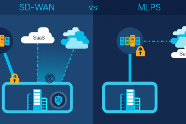
OSPF LSA filtering to routing table issue on ABR

Today I would like to show you strange OSPF ABR’s behaviour that denies the OSPF algorithm. Simple LSA filtering to routing table on ABR can break the LSA propagation to non-zero area.

First, let’s briefly recall the basic rules and operations of OSPF.

  • Adjacencies – routers exchange hello packets and establish neighbor adjacency.
  • Link-state advertisements – routers exchange LSAs that describe all of the router’s known links.
  • Link-state databes synchronization – by flooding LSAs throughout an area, all routers build identical link-state databases.
  • Building routing table based on SPF tree – once the databases are complete, routers run the SPF algorithm to calculate a loop-free topology describing the shortest path to every destination. Routing table is build based on the SPF tree.

After all link-state details have been flooded to all neighbors in an area and all have verified that their databases are identicalthat then the link-state databases have been synchronized and the route tables have been built.

Here I would to closer look at the ABR router, his function and operation.

Area Border Routers (ABRs) connect one or more areas to the backbone and works as a gateway for inter-area traffic. An ABR always has at least one interface that belongs to the backbone and maintain a separate link-state database for each connected areas.

Network Summary LSAs are originated by ABRs. They are sent into a single area to advertise destinations outside that area. ABR tells the internal routers of an attached area what destinations the ABR can reach. An ABR also advertises the destinations within its attached areas into the backbone with Network Summary LSAs

Once the ABR’s function and operation has been described let’s configure simple OSPF architecture with four routers which two are ABRs based on the below topology.

R1’s loopback has been added to Area 1. R2 and R3 are ABRs.
Let’s see how the R3 LS database looks like:

R3#sh ip ospf database
OSPF Router with ID (3.3.3.3) (Process ID 1)
Router Link States (Area 0)
Link ID ADV Router Age Seq# Checksum Link count
2.2.2.2 2.2.2.2 1033 0x80000006 0x00CFFD 1
3.3.3.3 3.3.3.3 1270 0x80000005 0x009332 1
Net Link States (Area 0)
Link ID ADV Router Age Seq# Checksum
10.0.23.2 2.2.2.2 1292 0x80000003 0x00A553
Summary Net Link States (Area 0)
Link ID ADV Router Age Seq# Checksum
1.1.1.1 2.2.2.2 1033 0x80000003 0x00899A
10.0.12.0 2.2.2.2 1033 0x80000007 0x009E70
10.0.34.0 3.3.3.3 1020 0x80000005 0x009165
Router Link States (Area 34)
Link ID ADV Router Age Seq# Checksum Link count
3.3.3.3 3.3.3.3 1020 0x80000004 0x00921D 1
4.4.4.4 4.4.4.4 937 0x80000004 0x005156 1
Net Link States (Area 34)
Link ID ADV Router Age Seq# Checksum
10.0.34.3 3.3.3.3 1021 0x80000003 0x005888
Summary Net Link States (Area 34)
Link ID ADV Router Age Seq# Checksum
1.1.1.1 3.3.3.3 1800 0x80000001 0x00D344
10.0.12.0 3.3.3.3 1021 0x80000003 0x00EC18
10.0.23.0 3.3.3.3 1271 0x80000003 0x000FF4


R4 gets 1.1.1.1/32 subnet as expected:

R4#sh ip ospf database summary 1.1.1.1
OSPF Router with ID (4.4.4.4) (Process ID 1)
Summary Net Link States (Area 34)
Routing Bit Set on this LSA
LS age: 1324
Options: (No TOS-capability, DC, Upward)
LS Type: Summary Links(Network)
Link State ID: 1.1.1.1 (summary Network Number)
Advertising Router: 3.3.3.3
LS Seq Number: 80000001
Checksum: 0xD344
Length: 28
Network Mask: /32
TOS: 0 Metric: 21
R4#sh ip route 1.1.1.1
Routing entry for 1.1.1.1/32
Known via "ospf 1", distance 110, metric 31, type inter area
Last update from 10.0.34.3 on FastEthernet0/0, 00:22:15 ago
Routing Descriptor Blocks:
* 10.0.34.3, from 3.3.3.3, 00:22:15 ago, via FastEthernet0/0
Route metric is 31, traffic share count is 1

OK let’s move to the LSA filtering to routing table on ABR router.

We have following options to filter out LSA from LSA database to routing table:

  • Distance with 255 administrative distance
  • Distribute list
  • Static route to null0 (route will appear in RT but effect will be the same like above – drop packets

First let’s take a look at R2 ABR and apply filtering option with distribute list to filter out the 1.1.1.1 subnet from the routing table.

R2(config)#access-list 2 deny 1.1.1.1
R2(config)#access-list 2 permit any
R2(config)#router ospf 1
R2(config-router)#distribute-list 2 in FastEthernet0/1

To confirm that 1.1.1.1 still appears as LSA3 in LSA DB on R2.

R2#show ip ospf database summary 1.1.1.1
OSPF Router with ID (2.2.2.2) (Process ID 1)
Summary Net Link States (Area 0)
LS age: 763
Options: (No TOS-capability, DC, Upward)
LS Type: Summary Links(Network)
Link State ID: 1.1.1.1 (summary Network Number)
Advertising Router: 2.2.2.2
LS Seq Number: 8000000C
Checksum: 0x77A3
Length: 28
Network Mask: /32
TOS: 0 Metric: 11

To confirm that 1.1.1.1 has been withdrawn from the routing table on the R2.

R2#sh ip route 1.1.1.1
% Network not in table

To confirm that 1.1.1.1 still appears as LSA3 in LSA DB on R3:

R3#show ip ospf database summary 1.1.1.1
OSPF Router with ID (3.3.3.3) (Process ID 1)
Summary Net Link States (Area 0)
Routing Bit Set on this LSA
LS age: 939
Options: (No TOS-capability, DC, Upward)
LS Type: Summary Links(Network)
Link State ID: 1.1.1.1 (summary Network Number)
Advertising Router: 2.2.2.2
LS Seq Number: 8000000C
Checksum: 0x77A3
Length: 28
Network Mask: /32
TOS: 0 Metric: 11
Summary Net Link States (Area 34)
LS age: 4
Options: (No TOS-capability, DC, Upward)
LS Type: Summary Links(Network)
Link State ID: 1.1.1.1 (summary Network Number)
Advertising Router: 3.3.3.3
LS Seq Number: 80000001
Checksum: 0xD344
Length: 28
Network Mask: /32
TOS: 0 Metric: 21

To confirm that 1.1.1.1 still appears in R3 and R4 routing table.

R3#sh ip route 1.1.1.1
Routing entry for 1.1.1.1/32
Known via "ospf 1", distance 110, metric 21, type inter area
Last update from 10.0.23.2 on FastEthernet0/1, 01:09:07 ago
Routing Descriptor Blocks:
* 10.0.23.2, from 2.2.2.2, 01:09:07 ago, via FastEthernet0/1
Route metric is 21, traffic share count is 1

R4#sh ip route 1.1.1.1
Routing entry for 1.1.1.1/32
Known via "ospf 1", distance 110, metric 31, type inter area
Last update from 10.0.34.3 on FastEthernet0/0, 01:08:45 ago
Routing Descriptor Blocks:
* 10.0.34.3, from 3.3.3.3, 01:08:45 ago, via FastEthernet0/0
Route metric is 31, traffic share count is 1

OK, all is working as expected. Let’s apply the same filtering rule on the R3 and see the diference.

R3(config)#access-list 2 deny 1.1.1.1
R3(config)#access-list 2 permit any
R3(config)#router ospf 1
R3(config-router)#distribute-list 2 in FastEthernet0/1

Routing table on R3 as expected, 1.1.1.1 has been withdrawn.

R3#sh ip route 1.1.1.1
% Network not in table

What about LSA database?

R3#show ip ospf database summary 1.1.1.1
OSPF Router with ID (3.3.3.3) (Process ID 1)
Summary Net Link States (Area 0)
Routing Bit Set on this LSA
LS age: 916
Options: (No TOS-capability, DC, Upward)
LS Type: Summary Links(Network)
Link State ID: 1.1.1.1 (summary Network Number)
Advertising Router: 2.2.2.2
LS Seq Number: 8000000C
Checksum: 0x77A3
Length: 28
Network Mask: /32
TOS: 0 Metric: 11

1.1.1.1 still appears for Area 0 as expected but what about Area34? Routes has been withdrawn from the Area34. What about R4, does it mean that R4 will not get this route anymore?

Let’s see the routing table and LSA database on R4.

R4#sh ip route 1.1.1.1
% Network not in table
R4#show ip ospf database summary 1.1.1.1
OSPF Router with ID (4.4.4.4) (Process ID 1)

Exactly, link has been withdrawn from LS database for area 34 on R4 once we applied LS filtering to the routing table on R3, good to know ;).

Let’s change the filtering option on R3 from distribute list to static route to null0.

R3(config)#router ospf 1
R3(config-router)#no distribute-list 2 in FastEthernet0/1
R3(config-router)#ip route 1.1.1.1 255.255.255.255 null 0

Let’s see what we have on R4 now:
R4#sh ip route 1.1.1.1
% Network not in table
R4#show ip ospf database summary 1.1.1.1
OSPF Router with ID (4.4.4.4) (Process ID 1)

OK so even if 1.1.1.1 exist in the routing table but is prefered by the non OSPF protocol (in this case by static) is not advertised by the ABR from area 0 to non-zero area.

Conclusion – OSPF ABR that doing LSAs propagation from the Area 0 to to non-zero area advertised to non-zero area only these LSAs that exist in the routing table and are marked as OSPF prefered routing protocol.

Let me know if you find about it in any OSPF RFC or Cisco documentation :).
Thanks to Narbik for mentoring.

Static inside and outside NAT example

In simplified way Network Address Translation (NAT) allow us to translate source or/and destination address of IP packet. There is few reasons to do it like managment purpose, security or IP address savings. NAT is one of technology that with success delays IPv6 world wide deployment. First of all let’s explain NAT wording that at first sight looks slightly confused. Below simple diagram will help us to understand the concept.

  • Inside local IP is how inside address is seen localy by inside hosts, so from the our LAN perspective it’s real IP of our PC. 
  • Inside global IP is how inside address is seen globaly by outside hosts, so from the outside hosts in Internet it’s translated (NATed) IP of our host. 
  • Outside local IP is how outside address is seen localy by inside hosts, so from the LAB perspective it’s translated (NATed) IP of host that resides out of our network like in Internet. Hosts in LAN will use it as destination IP address.
  • Outside global IP is how outside address is seen globaly by outside hosts, so from the our LAN perspective it’s real IP address of host that resides out of our network.

Inside translation type is frequently used in today’s networks. In case we have 10000 hosts in our LAN and would allow them to connect to the Internet resource then we need provide external public IP address for each internal hosts. So big range of public IP addresses expensive but sometimes even not be available for not service provider company. NAT is a solution in this example. We can simple translate all inside IP addresses to 1 public IP using Port Address Translation (PAT) NAT feature. The first question that comes to the mind is how the router will be able to distinguish the packets once they back from the Internet. PAT simply translate the IPs to one outside IP but additionaly translates the layer 4 source ports. Router initially simple rewrites the TCP or UDP source port changing just a source IP but in case another host intimates session with the same layer 4 source then router will take first free port. Based on this easy mechanism router is able to create around 64511 session for one public IP (we have 65535 ports where first 1024 are reserved). The second example of inside NAT is static one-2-one translation. Inside NAT allows us to hide the server real IP address (frequently used private IP range) and put it under public IP in the Internet as service for public use. Thanks to this we can hide our network infrastructure and additionaly again save our public IP range because all of our public services can be hosted under one IP.
The outside NAT translation changing destination IP address. It’s usful when our company has business connection to third party and they are using IP address that is already used in our network somewhere.

Let’s take a first example and try to configure inside and outside static NAT translation based on the below diagram.

First inside so source IP (from the LAN perspective) translation.
R2(config)#ip nat inside source static ?
A.B.C.D Inside local IP address
esp IPsec-ESP (Tunnel mode) support
network Subnet translation
tcp Transmission Control Protocol
udp User Datagram Protocol
R2(config)#ip nat inside source static 10.0.12.1 ?
A.B.C.D Inside global IP address
interface Specify interface for global address
R2(config)#ip nat inside source static 10.0.12.1 132.0.1.100

Inside done. All traffic from the PC with IP 10.0.12.1 will be NATed to the 132.0.1.100.
Next let’s define the server IP address (192.168.1.7) that will be used by local PC as destination IP.

R2(config)#ip nat outside source static ?
A.B.C.D Outside global IP address
network Subnet translation
tcp Transmission Control Protocol
udp User Datagram Protocol
R2(config)#ip nat outside source static 200.1.2.3 ?
A.B.C.D Outside local IP address
R2(config)#ip nat inside source static 10.0.12.1 132.0.1.100

We have to define the inside and outside interface.
R2(config)#int fa0/1
R2(config-if)#ip nat outside
R2(config-if)#int fa0/0
R2(config-if)#ip nat inside
R2(config-if)#no ip route-cache
R2#show ip nat translations
Pro Inside global Inside local Outside local Outside global
--- --- --- 192.168.1.7 200.1.2.3
--- 132.0.1.100 10.0.12.1 --- ---

OK all done. Two static one2one translation have been added to the NAT table. It’s worth to mention here that this type of entry is kinf of reversible translation type – it’s possible to initiate connection from inside or from outside. In case of dynamic NAT it’s impossible to initiate connection from outside unless dynamic NAT with route-map and reversible option at the end is used.

Let’s run the debug IP packet and initiate test traffic doing telnet to outside local IP address – 192.168.1.7 from the PC.

R2#debug ip packet detail
IP packet debugging is on (detailed)
*Mar 1 02:32:44.819: IP: s=10.0.12.1 (FastEthernet0/0), d=192.168.1.7, len 44, unroutable
*Mar 1 02:32:44.823: TCP src=35649, dst=23, seq=391750710, ack=0, win=4128 SYN
*Mar 1 02:32:44.827: IP: tableid=0, s=10.0.12.2 (local), d=10.0.12.1 (FastEthernet0/0), routed via FIB
*Mar 1 02:32:44.831: IP: s=10.0.12.2 (local), d=10.0.12.1 (FastEthernet0/0), len 56, sending
*Mar 1 02:32:44.835: ICMP type=3, code=1

Hmm 192.168.1.7 is unroutable, does it mean that router first take routing decision before translation.
Here you are short list of Cisco IOS order of operation: 

  1. If IPsec, then check input access list
  2. Decryption—for Cisco Encryption Technology (CET) or IPsec
  3. Check input access list
  4. Check input rate limits
  5. Input accounting
  6. Policy routing
  7. Routing
  8. Redirect to Web cache
  9. NAT
  10. Crypto (check map and mark for encryption)
  11. Check output access list
  12. Inspect context-based access control (CBAC)
  13. TCP intercept
  14. Encryption
  15. Queueing

OK let’s add routing to the 192.168.1.7 and see what happens.
R2#*Mar 1 03:23:34.311: IP: tableid=0, s=10.0.12.1 (FastEthernet0/0), d=192.168.1.7 (FastEthernet0/1), routed via FIB ---Routing over Fa0/1
*Mar 1 03:23:34.315: NAT: s=10.0.12.1->132.0.1.100, d=192.168.1.7 [318] --- source NAT
*Mar 1 03:23:34.319: NAT: s=132.0.1.100, d=192.168.1.7->200.1.2.3 [318] --- destination NAT
*Mar 1 03:23:34.323: IP: s=132.0.1.100 (FastEthernet0/0), d=200.1.2.3 (FastEthernet0/1), g=10.0.23.3, len 44, forward
*Mar 1 03:23:34.327: TCP src=31740, dst=23, seq=1913933555, ack=0, win=4128 SYN

R2#show ip nat translations
Pro Inside global      Inside local       Outside local      Outside global
--- ---                ---                192.168.1.7        200.1.2.3
tcp 132.0.1.100:31740  10.0.12.1:31740    192.168.1.7:23     200.1.2.3:23
--- 132.0.1.100        10.0.12.1          ---                ---

Connection initiated successfully. First SYN packet is routed and will be push out over Fa0/1 (red), next inside (source) and outside (destination) NAT is taking place. TCP source and destination ports 31740 and 23 respectively have been written in NAT translation table. Enjoy the NAT.